Ceramic and Metal Component Prototyping
~ Functional Prototypes and Production ~
| Microfluidics | Materials | Technologies | Contact | Sending Files | About CAM-LEM | Home |
| CAM-LEM Process |
Green Machining |
Inteform Process |
Green Casting |
|||
| Microfluidics | Materials | Technologies | Contact | Sending Files | About CAM-LEM | Home |
| CAM-LEM Process |
Green Machining |
Inteform Process |
Green Casting |
|||
| The CAM-LEM Process
CAM-LEM's Inteform Thinsheet process originates in a CAD model decomposed into boundary contours of thin slices. The component is developed in a layered manner, then post-processed to yield optimum mechanical and surface properties.
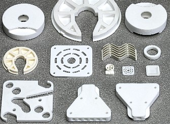
In CAM-LEM individual slices of sheet stock engineering material (such as "green" ceramic tape) are laser-cut per the computed contours. The resulting part-slice regions are extracted from the sheet stock and stacked to assemble a physical 3-D realization of the original CAD description. The assembly operation includes a tacking procedure that fixes the position of each sheet relative to the pre-existing stack.
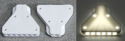
After assembly, the layers are laminated together to achieve intimate inter-layer contact, promoting high-integrity bonding in the subsequent sintering operation. The laminated "green" object is then fired to densify the object into a monolithic structure. During this step the laminated history is completely erased and components offer material properties equivalent to those of standard manufacturing methods. The result is a 3-D part which exhibits not only correct geometric form, but functional structural behavior as well.
 The CAM-LEM process features:
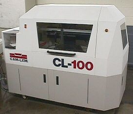
 The CL-100 Machine This machine automates the layered prototyping process.
The CL-100 produces parts or sets of parts within its
150 mm (6") cube work envelope.
|
|||||||||||||||||||||||||